200以上 angularity symbol 217832-Angularity symbol
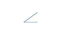
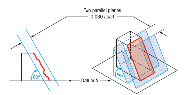
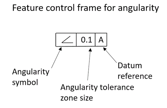
The angularity control keeps the angle of a feature with respect to the datum in check We can use it to control a 2D line, but it is more popular with keeping surfaces (3D) under control This kind of tight control keeps the angle and the surface flatness in check and is recommended for part features that mate with other parts through theAngularity Angularity tolerance symbol is shown as "∠"Angularity tolerance specifies a tolerance zone defined by two parallel plane at the specified angle other than 90 degree from a datum plane or axis within where the surface or the axis of the feature must lie1 The tolerance zone is cylindrical
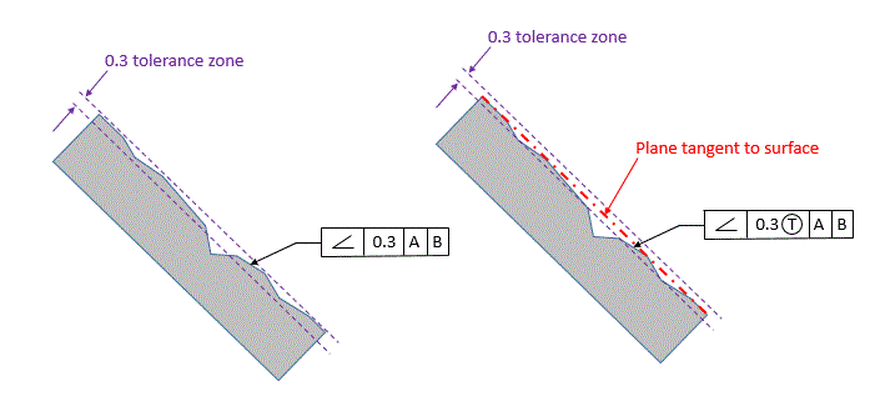
Angularity Dimensional Consulting
Angularity symbol
Angularity symbol-GD&T Symbol Relative to Datum Yes MMC or LMC applicable Yes (Uncommon) Drawing Callout Description Angularity is the symbol that describes the specific orientation of one feature to another at a referenced angle It can reference a 2D line referenced to another 2D element, but more commonly it relates the orientation of one surface planeHow to Use Symbols First select the symbol then you can drag&drop or just copy&paste it anywhere you like AltCodes can be typed on Microsoft Operating Systems First make sure that numlock is on, Then press and hold the ALT key, While keeping ALT key pressed type the code for the symbol that you want and release the ALT key
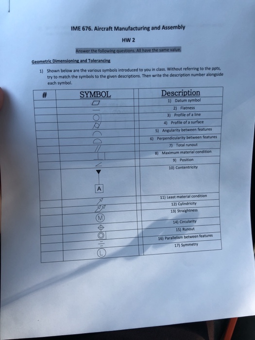


Solved Me 676 Aircraft Manufacturing And Assembly Hw 2 G Chegg Com
GD&T Symbol Relative to Datum Yes MMC or LMC applicable Yes (Uncommon) Drawing Callout Description Angularity is the symbol that describes the specific orientation of one feature to another at a referenced angle It can reference a 2D line referenced to another 2D element, but more commonly it relates the orientation of one surface planeThe "all over" symbol is new it means that the given tolerance (profile) applies to all surfaces of the part The "all around" symbol has been around for years (a single circle), but it only applied the tolerance to the perimeter in a given view See paragraph 16 CF CF stands for "continuous feature"Angularity One Orientation Symbol Tangent Plane Chapter 8 Profile Between Symbol All Around Symbol General Profile Tolerances Unequal Profile Tolerance Composite Profile Tolerancing Coplanarity NonUniform Zone Position and Symmetry Position Composite and SingleSegment Inspecting Position Symmetry
Angularity One Orientation Symbol Tangent Plane Chapter 8 Profile Between Symbol All Around Symbol General Profile Tolerances Unequal Profile Tolerance Composite Profile Tolerancing Coplanarity NonUniform Zone Position and Symmetry Position Composite and SingleSegment Inspecting Position SymmetryAngularity Angularity is the condition of a surface, axis, or center plane, which is at a specified angle (other than 0, 90, 180 or 270 deg) from a datum plane or axis Symbol All Around Indicates that a tolerance applies to surfaces profile all around the part outlineIn geometric dimensioning and tolerancing (GD&T), a unique set of GD&T symbols are used to define the relationships between part features and measurement references Designers and engineers utilize this international language on their drawings to accurately describe part features on the basis of size, form, orientation and location
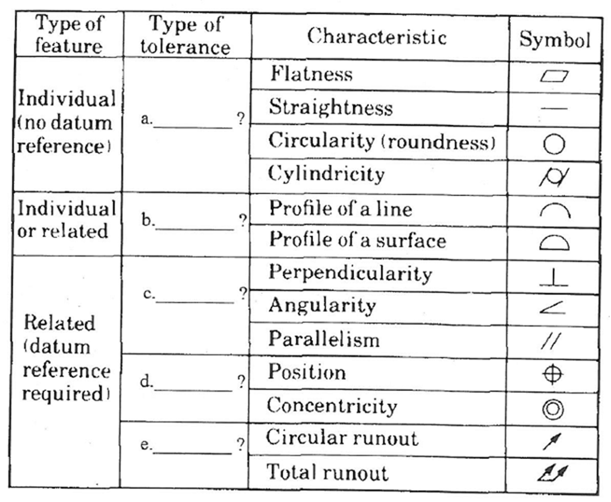
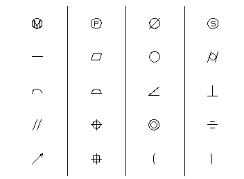
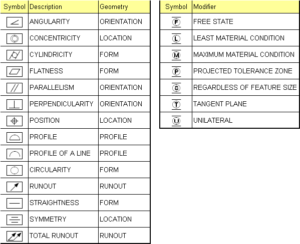
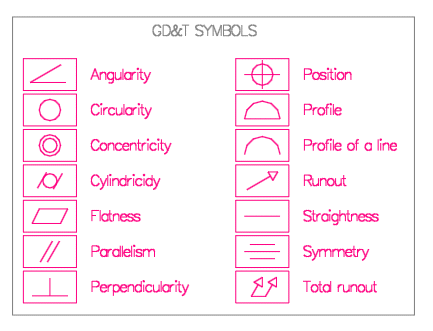
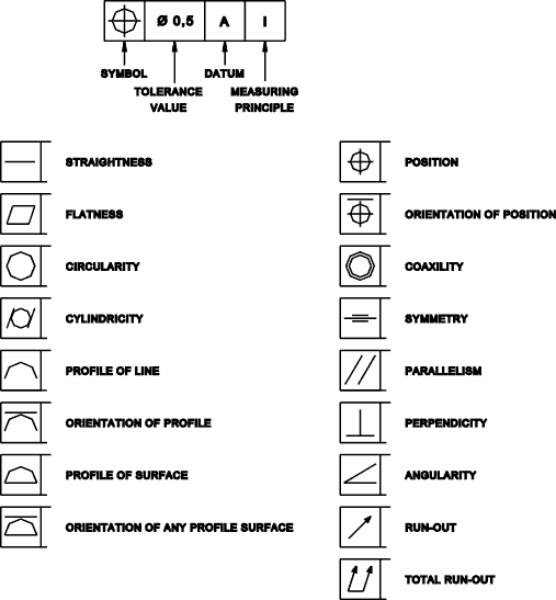
Angularity Pro˜le of a line True Position Concentricity Symmetry Runout Total Runout Pro˜le of a surface True Position (Maximum Material Condition) Flatness (Derived Median Plane w/ )M M M M M SYMBOL NAME ON DRAWING TOLERANCE ZONE GAUGING GD&T Symbols and Guidelines Cheat SheetIn this video you learn gd&t in tamil detail if you like the video Subscribe,share,like and comments gd&t gd&t symbols gd&t pdf gd&t basics gd&t training gThe symbol is inserted into the Sym text box in the Geometric Tolerance dialog box The following table describes the symbols Angularity Orientation Cylindricility Form Flatness Form Circularity or roundness Form Straightness Form Profile of a surface Profile Profile of a line Profile Circular runout Runout


True Position Gd T Basics
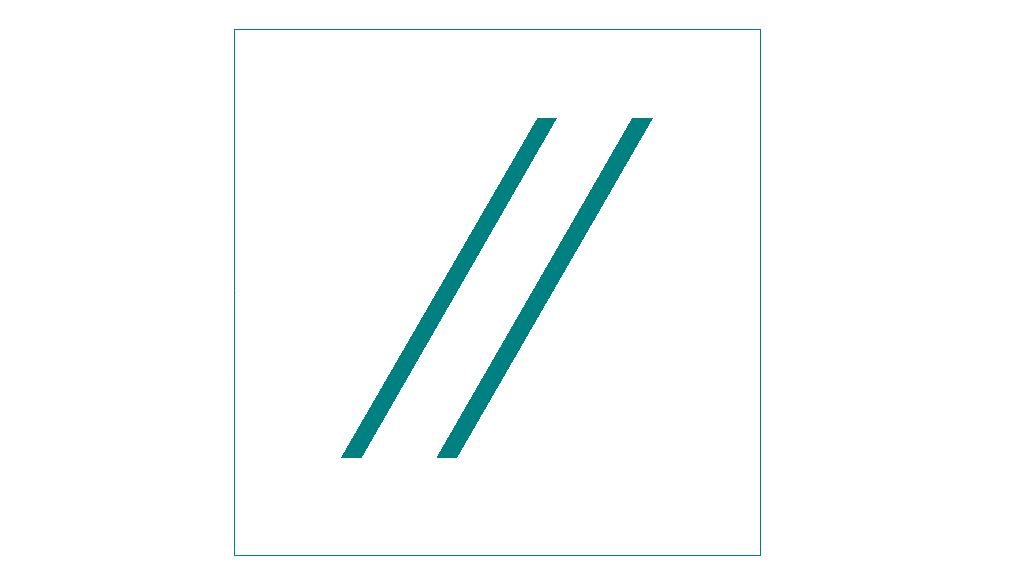


Geometric Dimensioning Tolerancing Gd T Symbols Basics
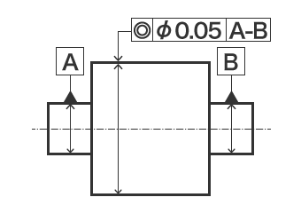
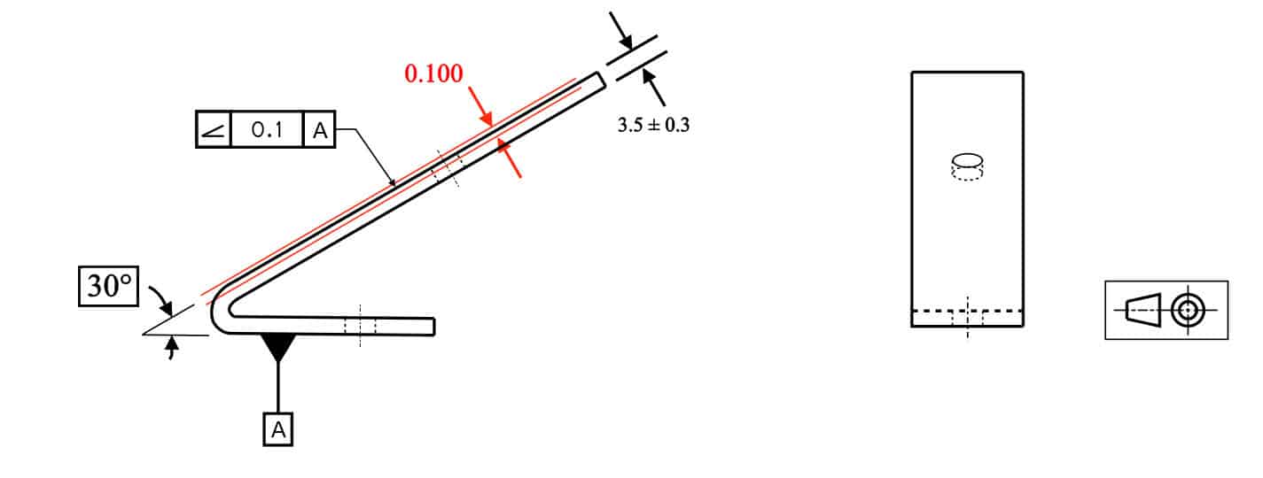
Allowed Modifiers When the considered feature is a cylinder or a width, angularity allows a maximum material modifier to indicate the specification is at the maximum material condition (MMC) Alternatively, it allows a least material modifier to indicate the specification is at the least material condition (LMC) This means that as the unrelated mating envelope size (or unrelated minimumAngularity Describes the specific orientation of one feature to another at a referenced angle Symmetry The all inclusive symbol for surfaces profile tolerances can control the size, location, orientation or form of any surface feature RunoutWith angularity, we must always have a datum reference and a basic angle Note that this time we have both datums A and B called out in order to control the angles to both datum A and datum B The angle to datum A is explicitly called out with the 45 degree basic angle The angle to datum B is an implied basic 90 degree angle


Angularity Gd T Basics
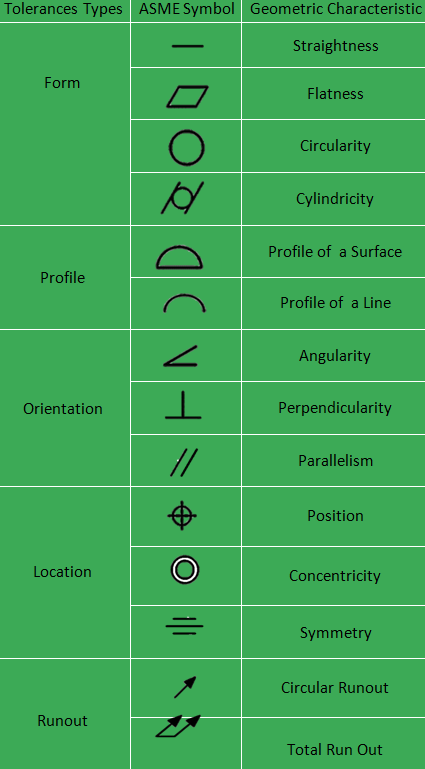


Gd T The Beginner S Guide To Geometric Dimensioning And Tolerancing
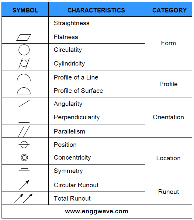
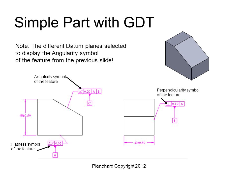
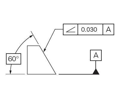
The GD&T symbols are classified into five groups as below Check out these GD&T terms and definitions 1 Form controls Straightness a tolerance that controls the form of a line somewhere on the surface or the feature Angularity specifies a tolerance zone defined by two parallel planes at the specified angle other than 90 degrees from aThe datum translation symbol is the triangle shown in the far right box of the feature control frame above It indicates that the datum feature simulator for the F datum is free to translate Angularity requires that the surface be between two parallel planes that are 2 millimeters apart and exactly degrees from datum BGeometric dimensioning and tolerancing (GD&T) is a system for defining and communicating engineering tolerances It uses a symbolic language on engineering drawings and computergenerated threedimensional solid models and its allowable variation


Angularity Dimensional Consulting
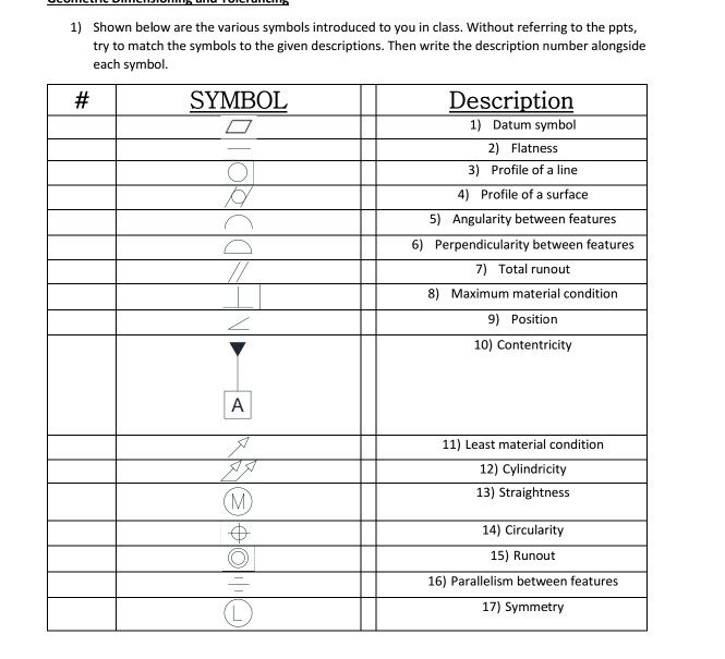


Solved 1 Shown Below Are The Various Symbols Introduced Chegg Com
333 Angularity Angularity is indicated by two lines forming a 30° angle See Figure 25 Figure 25 Angularity Symbol 34 LOCATION Position tolerances are the most common location tolerance Concentricity and symmetry are also types of location tolerances Profile tolerances can be used to control location, but these are covered separatelyAngularity is the symbol that describes the specific orientation of one feature to another at a referenced angle It can reference a 2D line referenced to another 2D element, but more commonly it relates the orientation of one surface plane relative to another datum plane in a 3Dimensional tolerance zoneAngularity/Ø0100m/B/A is a legit callout (ref TecEase video) I declare WAR on anyone who says otherwise B does not affect final measured deviation, but it does give you better picture of deviation direction
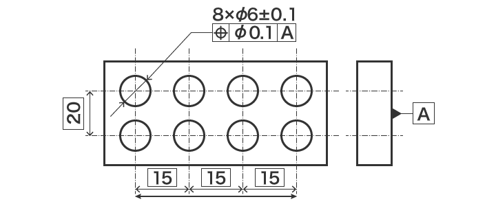


Gd T Drawings And Symbols Gd T Overview Gd T Fundamentals Keyence America


Index Of Pdf Files Gd T Symbols
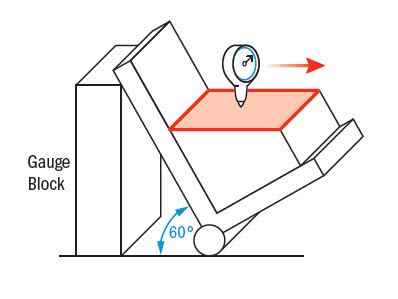
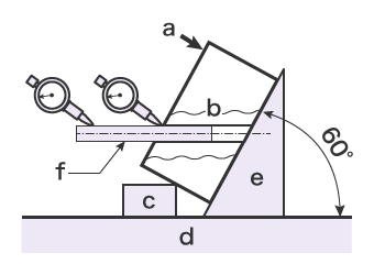
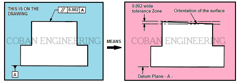
Orientation tolerance determines the orientation for the form in relation to a reference This section explains the symbols of three geometrical characteristics, ie parallelism, perpendicularity, and angularity, in an easytounderstand manner, using sample drawing indications "Learning GD&T From Scratch," provided by KEYENCE, walks you through the basics of geometric dimensioning andAngularity is the symbol that describes the specific orientation of one feature to another at a referenced angle It can reference a 2D line referenced to another 2D element, but more commonly it relates the orientation of one surface plane relative to another datum plane in a 3Dimensional tolerance zoneGeorge C Wang, in The Utilization of Slag in Civil Infrastructure Construction, 16 Coarse aggregate angularity Coarse aggregate angularity is determined by computing the percentage of coarse aggregate particles with fractured faces A sample of coarse aggregate is divided into three groups One group contains all the particles with no fractured face, the second group contains all


Http Www Proofengineering Com White Papers Introduction to geometric dimensioning and tolerancing Pdf


1
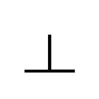
In GD&T the Angularity symbol is used to reference how one feature is oriented to another at a referenced angle For example, it could reference the orientation of a surface plane relative to a datum plane in a 3D tolerance zone, or it could referene the relationship of a 2D line to another 2D element Note that Angularity only indirectly controls the tolerance for the actual angle, which will normally be directly controlled by a plus/minus toleranceThe definitions for angularity, perpendicularity, and parallelism are all in one paragraph, and the text applies to all of the orientation tolerances A Angularity Symbol The use of the angularity symbol meaning orientation is introduced as an alternative practice to using perpendicularity and parallelismThis page shows a list of GD&T symbols and associated symbols used by ISO and ASME "Learning GD&T From Scratch," provided by KEYENCE, walks you through the basics of geometric dimensioning and tolerancing, datums, and measurements by coordinate measuring machines It also introduces techniques for visitors who want to learn more


Gd T Symbols Reference Guide From Sigmetrix Mechanical Engineering Design Mechanical Symbols Engineering Symbols
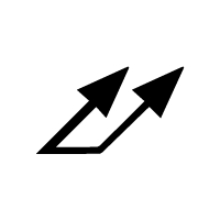


Gd T Geometric Dimensioning And Tolerancing
Angularity definition is the quality of being angular Recent Examples on the Web Honja's living room wall looks dapper with an impromptu blackandgray scallop pattern that offsets the angularity of her sofa — Kathy Barnes, Better Homes & Gardens, "PaintPen Murals and Stenciled Designs Fill This Home with a Riot of Color," 23 Feb 21 Note his lines — their fluidity, their angularityIn an angularity control, when a diameter symbol is specified before the tolerance value, the shape of the tolerance zone is what?How to Use Symbols First select the symbol then you can drag&drop or just copy&paste it anywhere you like AltCodes can be typed on Microsoft Operating Systems First make sure that numlock is on, Then press and hold the ALT key, While keeping ALT key pressed type the code for the symbol that you want and release the ALT key


Geometric Dimensioning And Tolerancing Gd T


16 Angularity Angle Engineering Tolerance
Angularity is the symbol that describes the specific orientation of one feature to another at a referenced angle Concentricity Concentricity, sometimes called coaxially, is a tolerance that controls the central axis of the referenced feature, to a datum axis circularitySymbol Name Description Straightness Straightness is how close to a straight line a feature is Flatness Angularity is the same as perpendicularity with the exception that the two features are not at 90 degrees to one another but instead at a different specified angleOrientation Angularity Controls orientation of a feature at a specific angle in relation to the primary datum of its datum reference frame · Orientation Parallelism Controls orientation of a feature which is nominally parallel to the primary datum of its datum reference frame ¿ Controls the location Location Position


Wallet Sized Gd T Symbol Reference Card Omnia Mfg
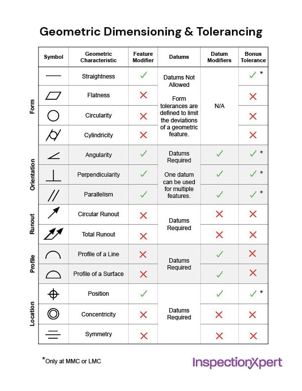


Gd T Geometric Dimensioning And Tolerancing
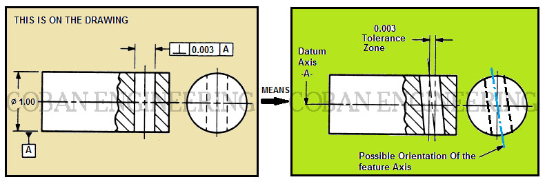
Orientation Angularity Controls orientation of a feature at a specific angle in relation to the primary datum of its datum reference frame · Orientation Parallelism Controls orientation of a feature which is nominally parallel to the primary datum of its datum reference frame ¿ Controls the location Location PositionGeometric Dimensioning and Tolerancing (GD&T) is a system for defining and communicating engineering tolerancesIt uses a symbolic language on engineering drawings and computergenerated threedimensional solid models that explicitly describe nominal geometry and its allowable variation It tells the manufacturing staff and machines what degree of accuracy and precision is needed on eachAngularity Symbol drawing call out Perpendicularity Perpendicularity defines the amount of deviation between two surfaces when theoretically both should be perpendicular Ideally, perpendicularity can also be defined with angularity with a 90degree angle But its an industry practice to use perpendicularity when two surfaces are having a 90


Gd T 101 An Introduction To Geometric Dimensioning And Tolerancing


Keycreator Help Special Symbols For Dimension Text
George C Wang, in The Utilization of Slag in Civil Infrastructure Construction, 16 Coarse aggregate angularity Coarse aggregate angularity is determined by computing the percentage of coarse aggregate particles with fractured faces A sample of coarse aggregate is divided into three groups One group contains all the particles with no fractured face, the second group contains allWith angularity, we must always have a datum reference and a basic angle Note that this time we have both datums A and B called out in order to control the angles to both datum A and datum B The angle to datum A is explicitly called out with the 45 degree basic angle The angle to datum B is an implied basic 90 degree angleNo copyright infringement intended All the rights go to their respective owners


Gd T Geometric Dimensioning And Tolerancing Orientation Tolerances Perpendicularity Angularity Parallelism


Geometric Tolerance Symbols Download Scientific Diagram
Angularity is flatness at an angle to a datum and is also determined through two reference planes spaced the tolerance value apart Perpendicularity means flatness at 90 degrees to a datum It specifies two perfect planes the feature plane must lie in betweenAngularity Describes the specific orientation of one feature to another at a referenced angle Symmetry The all inclusive symbol for surfaces profile tolerances can control the size, location, orientation or form of any surface feature RunoutAngularity Pro˜le of a line True Position Concentricity Symmetry Runout Total Runout Pro˜le of a surface True Position (Maximum Material Condition) Flatness (Derived Median Plane w/ )M M M M M SYMBOL NAME ON DRAWING TOLERANCE ZONE GAUGING GD&T Symbols and Guidelines Cheat Sheet


Easy Guide To Gd T Angularity Symbol Tolerance Measurement


Ebook Implementation Products Robotics And Other Useful Things
DefinitionsThe definitions of Angularity, Parallelism, and Perpendicularityare unchanged from ASME Y145M1994 In that revision the description of the a few orientation tolerances and their tolerance zones was repeated for every of the a few sorts of tolerance The only distinction involving the a few descriptions was the conditions angularity, parallelism, or perpendicularityOne radian is the angle subtended by an arc of a circle that has the same length as the circle's radius The radian is the derived quantity of angular measurement in the SI system By definition, it is dimensionless, though it may be specified as rad to avoid ambiguity Angles measured in degrees, are shown with the symbol °Subdivisions of the degree are minute (symbol ′, 1′ = 1/60The angularity symbol is often used to insure that the part can properly mate with another In GD&T, the degree of permissible variation is not specified as a tolerance on the angle Rather an indirect method is used where one specifies a tolerance zone at a specified angle from a datum, within which a part feature, axis, or center plane must lie


Runout Gd T Basics


Easy Guide To Gd T Angularity Symbol Tolerance Measurement
Angularity is flatness at an angle to a datum and is also determined through two reference planes spaced the tolerance value apart Perpendicularity means flatness at 90 degrees to a datum It specifies two perfect planes the feature plane must lie in betweenAngularity is the symbol that describes the specific orientation of one feature to another at a referenced angle Concentricity Concentricity, sometimes called coaxially, is a tolerance that controls the central axis of the referenced feature, to a datum axis circularityThe angularity control keeps the angle of a feature with respect to the datum in check We can use it to control a 2D line, but it is more popular with keeping surfaces (3D) under control This kind of tight control keeps the angle and the surface flatness in check and is recommended for part features that mate with other parts through the


Geometrical Tolerance An Overview Sciencedirect Topics


Angularity Gd T Basics
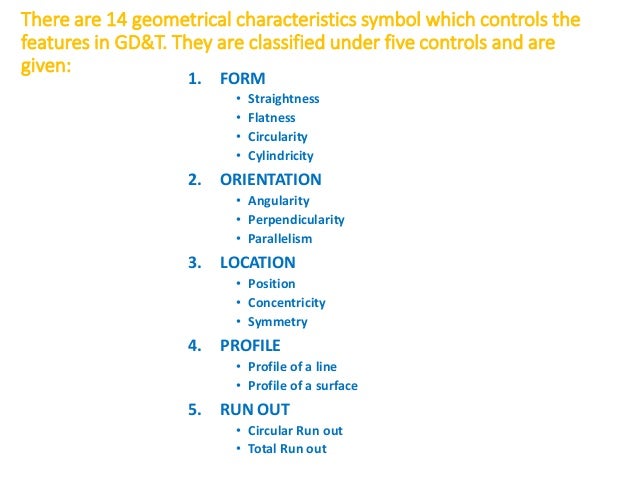
1 Symbols of GD&T (in detail) SREELAKSHMY VU (BE) 2 There are 14 geometrical characteristics symbol which controls the features in GD&T They are classified under five controls and are given 1 FORM • Straightness • Flatness • Circularity • Cylindricity 2 ORIENTATION • Angularity • Perpendicularity • Parallelism 3Cylindrical When angularity is applied to a cylindrical feature of size with a diameter symbol preceding the tolerance value, what conditions apply?Optional Angularity symbol may be used for all orientation controls Parallelism Angularity Location Position Locates center points, axes and median planes for size features Can also control orientation Profile of a Surface Locates surfaces


Gd T Symbols Reference Guide From Sigmetrix


Gd T Symbols Gd T Terms Geometric Dimensioning And Tolerancing Glossary Gd T Free Resource


Measuring Angularity Measuring With Datums Orientation Tolerance Gd T Fundamentals Keyence America


Gd T Symbols Gd T Terms Geometric Dimensioning And Tolerancing Enggwave Com
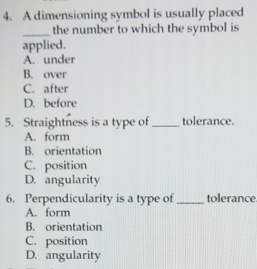


Solved 4 A Dimensioning Symbol Is Usually Placed The Num Chegg Com


Enotes Design
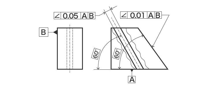


Measuring Angularity Measuring With Datums Orientation Tolerance Gd T Fundamentals Keyence America


The Vector Stencils Library Dimensioning And Tolerancing Contains 45 Symbols Of Geometric Dimensions Geometric Tolerancing Geometric Symbols Design Elements


Right Angle Wikipedia


Q Tbn And9gcrktg16usxcifuru6gyyefjx0r1i Ynfh6za7gidggcwa2jjnqd Usqp Cau
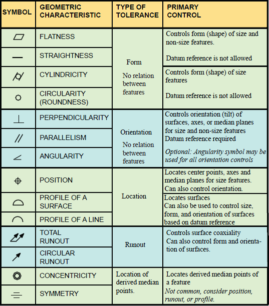


Gd T Symbols Charts For Engineering Drawing Drafting Geotol


How Gd T Form Tolerances Affect Shaft Fits Misumi Blog


Gd T Symbols Gd T Terms Geometric Dimensioning And Tolerancing Glossary Gd T Free Resource
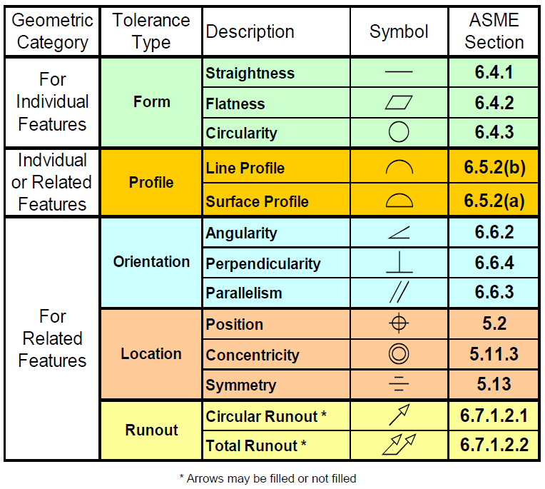


Common Gd T Symbols Dcs Gd T


Gd T Symbols Gd T Terms Geometric Dimensioning And Tolerancing Glossary Gd T Free Resource


Mechanical Engineering Solution Mechanical Engineering Design Technical Drawing Mechanical Engineering


Solved Type Of Type Of Feature Tolerance Individual No D Chegg Com


Gd T Geometric Dimensioning And Tolerancing Orientation Tolerances Perpendicularity Angularity Parallelism


Gd T Symbols Gd T Terms Geometric Dimensioning And Tolerancing Glossary Gd T Free Resource


14 Symbols Of Gd T


Solved Show The Geometric Tolerance Symbol Asme Y14 5 Chegg Com


Gd T Symbols In Excel Template


Geometric Dimensioning And Tolerancing Manufacturinget Org


Drafting And Dimensioning Symbols


Geometric Dimensioning And Tolerancing Course Number Instructor S Name Planchard Copyright Ppt Download


Www Abdiecasting Com Wp Content Uploads 17 09 Section 05 Geometric Dimensioning Pdf


Angularity Gd T Basics


File Gd T Png Wikipedia


Solved An 5 Match Symbol With Correct Characteristic Sy Chegg Com


7 Engineering Symbols Ideas Engineering Symbols Engineering Mechanical Engineering Design


Http Www Pages Drexel Edu Rcc34 Files Teaching Mem1 l6 Tolerance Rc Pdf


Gd T Geometric Dimensioning And Tolerancing


Gd T Symbols Reference Guide From Sigmetrix


Common Datums And Datum Systems Understanding Datums Gd T Fundamentals Keyence America


Geometric Dimensioning And Tolerance Gd T Symbols Mechcadcam Com


Gd T Tip Watch The Placement Of Datum Identification Symbols And The Feature Control Frames For Straightness Perpendicularity Parallelism And Angularity 09


Solved Me 676 Aircraft Manufacturing And Assembly Hw 2 G Chegg Com


16 Gd T Angularity Flashcards Quizlet


Gd T Symbol Relative To Datum Yes Mmc Or Lmc Applicable Yes Uncommon Drawing Callout Space Geometry


Gd T Symbols Reference Guide From Sigmetrix


Xwszib0nr2adtm


Geometric Dimension And Tolerance Description With Drawing Projection


1


Gd T Cad Symbols Emachineshop Cad Emachineshop


Gd T Geometric Dimensioning And Tolerancing Orientation Tolerances Perpendicularity Angularity Parallelism


Gd T Tips Datum


Angularity Dimensional Consulting


Geometrical Tolerances Roy Mech


Angularity Gd T Basics


Gd T Tolerance Zone Control Symbols


Gdt Symbols Reference


Gd T Application And Interpretation 6th Edition Page 23 23 Of 400


Geometric Tolerance Symbol Symbols Cards Positivity


Gd T Angularity Ptc Community


Gd T Symbols Flashcards Quizlet


Gd T Symbols Reference Guide From Sigmetrix


Pin On Mmm


Gd T Symbols Answers Mechanical Engineering Design Mechanical Engineering Work Geometric Tolerancing



Angularity Gd T Basics


Why Use Geometric Dimensioning Tolerancing Gd T Technia
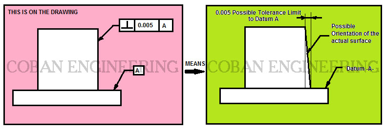


Gd T Geometric Dimensioning And Tolerancing Orientation Tolerances Perpendicularity Angularity Parallelism
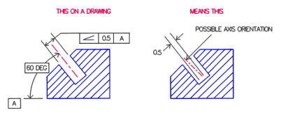


Gd T Angularity Definition Emachineshop


The Basics Of Geometric Dimensioning And Tolerancing Gd T Formlabs


Top Gd T Interview Questions And Answers For Mechanical Engineers


Gd T Symbols Reference Guide From Sigmetrix


Wallet Sized Gd T Symbol Reference Card Omnia Mfg


Gd T Symbols Gd T Terms Geometric Dimensioning And Tolerancing Glossary Gd T Free Resource


Q Tbn And9gcrlxjfvy4nmtcd0tfvmv8r9k0izkeixyaolnarabra Usqp Cau
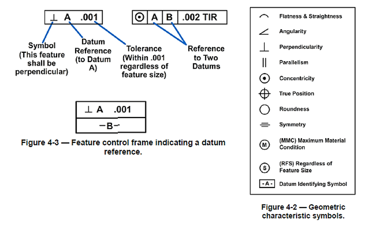


Machine Drawings Computer Aided Drafting Design
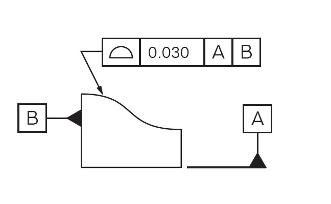


Profile Of A Surface Gd T Basics


16 Gd T Angularity Flashcards Quizlet


Geometric Dimensioning Tolerancing Symbols Design Study Com


Learn Gd T Completely In Tamil Geometric Dimensioning And Tolerancing Youtube


Angularity Gd T Basics


Www Abdiecasting Com Wp Content Uploads 17 09 Section 05 Geometric Dimensioning Pdf


18 Solidworks Help Geometric Tolerance Properties


19 Solidworks Help Creating Custom Symbols


Gd T Geometric Dimensioning And Tolerancing


コメント
コメントを投稿